 |
| Vapor compression refrigeration |
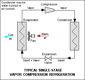
The thermodynamics of the cycle can be analyzed on a diagram as shown follow. In this cycle , a circulating refrigerant such as Freon enters the compressor as a vapor. The vapor is compressed at constant entropy and exits the compressors superheated. The superheated vapor travel through the condenser which first cools and removes the superheat and then condenses the vapor into a liquid by removing additional heat at constant pressure and temperature. The liquid refrigerant goes through the expansion valve (also called a throttle valve) where its pressure abruptly decreases , causing flash evaporation and auto-refrigeration of , typically , less than half of the liquid.
 |
| Temperature–Entropy diagram |
That results in a mixture of liquid and vapor at a lower temperature and pressure. The cold liquid-vapor mixture then travels through the evaporator coil or tubes and is completely vaporized by cooling the warm air (from the space being refrigerated) being blown by a fan across the evaporator coil or tubes. The resulting refrigerant vapor returns to the compressor to the compressor inlet to complete the thermodynamic cycle.
The above discussion is based on the ideal vapor-compression refrigeration cycle and does not take into account real-world effects like frictional pressure drop in the system , slight thermodynamic irreversibility during the compression of the refrigerant vapor or non-ideal gas behavior (if any).